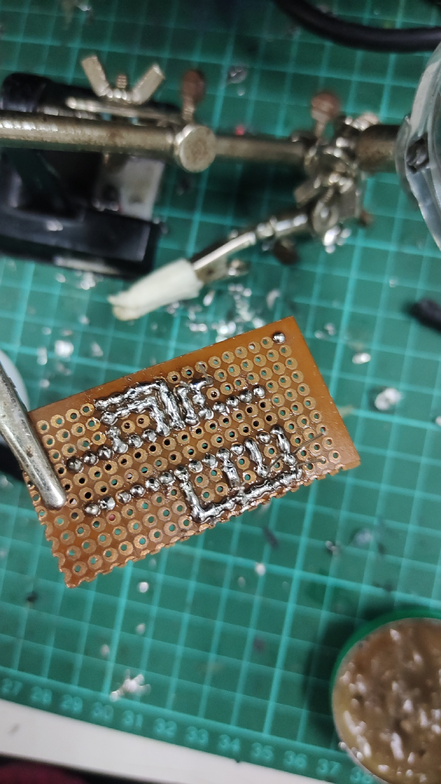
The objective of this project is to make the LED light up as the throttle is increased.
Procedures
1. The AT Mega 328 is programmed
2. The components such as the 28 pins socket, crystal oscillator, and LED bulb are soldered
3. The AT Mega 328 is attached to the 28-pin socket.
4. Test the project.
The diagram below shows the mapping of AT Mega 328 to Arduino UNO
The figure below shows the testing result of the project and additional information of the project
The link below is the testing for the project Link: https://www.youtube.com/shorts/IsSw7iAAW2k
Thanking Encik Zihad for guiding me in this project. Hoping to use and apply this application in more projects to come
The code below is used to light up the LED using the Throttle
const int pwmPin = 2; // Replace with the actual pin number
void setup() {
Serial.begin(9600); // Initialize serial communication for debugging
pinMode(9, OUTPUT);
pinMode(11, OUTPUT);
pinMode(13, OUTPUT);
}
void loop() {
// Read the PWM signal's pulse duration
unsigned long pulseDuration = pulseIn(pwmPin, HIGH);
// Print the duty cycle to the Serial Monitor
Serial.print("pwpPin: ");
Serial.println(pulseDuration);
delay(1000); // Delay for readability (adjust as needed)
if (pulseDuration > 1700){
digitalWrite(13, HIGH);
digitalWrite(11,HIGH);
digitalWrite(9,HIGH);
//delay(1000);
}else if (pulseDuration > 1500){
digitalWrite(13, HIGH);
digitalWrite(11,HIGH);
digitalWrite(9,LOW);
//delay(1000);
}else if (pulseDuration > 1200){
digitalWrite(13, HIGH);
digitalWrite(11,LOW);
digitalWrite(9,LOW);
}else {
digitalWrite(13, LOW);
digitalWrite(11,LOW);
digitalWrite(9,LOW);
}
}


Comments
Post a Comment